- Welcome to 2 STROKE WORLD .net.
2 STROKE WORLD

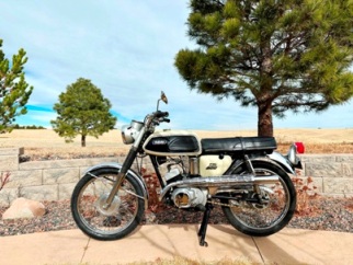
Rizingson's stunning YASC-1
Started by rd400canuck, October 11, 2021, 11:25:49 AM
Previous topic - Next topic0 Members and 1 Guest are viewing this topic.
Page created in 0.333 seconds with 15 queries.